
Bandmaster V
 Order Bandmaster V -
$295
Order Bandmaster V -
$295
*
Jumper free configuration
* Built-in USB interface
* RS-232, CI-V and band data interfaces
* USB connection to Flex SDR radios
* 12 programmable relay outputs
* Generates Icom CI-V data stream from Non-Icom radios
* Generates Yaeso & Kenwwod data stream from Icom radios
* Bi-directional band data interface
* Automatic antenna selection for each band
* Field upgradable firmware
* Dimensions 1.4" x 6.7" x 6.7" (HWD)
* Weight 1.2 pounds
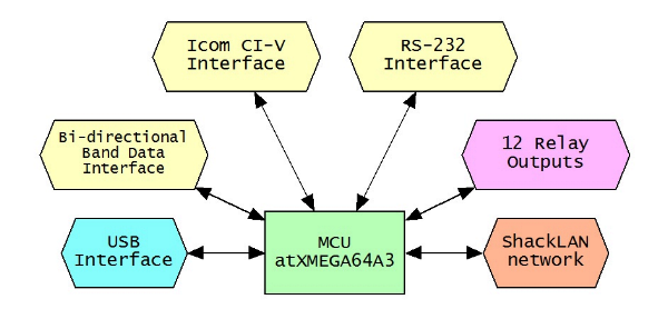
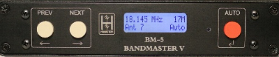
The BM-5 BandMaster V is a full featured unit that contains a
universal band decoder and antenna switch controller. It features five
communication channels. All channels are active simultaneously and
provide data translation for your station accessories. In other words,
if you are using an Icom radio on the CI/V interface the BandMaster V
will output 4-bit band data as well as RS-232 data in Yaesu or Kenwood
format. In reverse, when using a radio on the RS-232 interface the
BandMaster V will out 4-bit band data as well as an Icom CI/V data
stream.
The USB interface may be connected to your PC for radio control. The USB
interface may be connected directly to a Flex SDR with no additional
cables or interfaces required.
The BandMaster V contains a fully bi-directional band data interface.
The band data interface operates in input mode when using band data from
a Yaesu or Elecraft radio. When operating in band data mode the
BandMaster V will output data on both the CI/V and RS-232 interfaces
with the frequency fixed to the middle of the current band. The band
data interface operates in output mode when any of the other data
interfaces are used for your radio.
Configuring the BandMaster V is easily done from the front panel. No PC
software is required. Antennas are easily assigned to each band. No
diode matrix is needed for antennas used on multiple band.
The BandMaster V has 12 relay outputs which can configured in up to 16
different combinations. Any combination may be assigned as the default
antenna for each band.
Installation
Before you begin
Installing and configuring the BM-5 BandMaster V is a simple process. All configuration is done from the front panel. Configuration may also be done from a PC starting with v3 firmware. Installation and configuration steps are listed below.
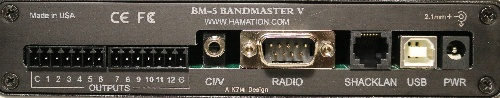
Power and network connections
The first step in the installation of the BM-5 is to connect 12vdc power to the unit. This can be done using either the power jack or via either ShackLAN jack from another device on the network. More information for the network and power connections are here.
USB connector
The USB connector is used to transfer data to and from the radio to your computer using a standard USB cable. It is also used to update the firmware. The USB may also be connected directly to Flex SDR radios. The USB driver should automatically install itself. If it does not, drivers can be downloaded at https://ftdichip.com/drivers/.
CI-V connector
This connector is used to interface to Icom radios. It uses the standard 1/8" phone plug used on all Icom radios for computer control. It should be connected to the REMOTE jack on Icom radios. For other makes of radios a CI-V data stream is sent from this connector to allow control of external devices.
Radio connector
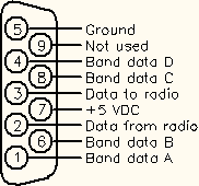 This connector is used to interface to all radios except Icom. You can
use the same cable you would normally connect between the radio and a
computer except when using the band data outputs from Yaesu and K3
radios. It is preferred that you use the RS-232 data from the radio and
not the band data outputs otherwise there will be reduced functionality.
If you still wish to use the band data outputs, you will need to make
your own interface cable or purchase a custom cable. Band data signals
are labeled A, B, C, D in most radio manuals but may be designated as 1,
2, 3, 4 or 1, 2, 4, 8. Pinouts for the radio connector are shown in the
diagram to the right. Consult your radio manual for pinouts on the radio
connector. When acquiring radio data from the CI-V, USB or band data
this connector will transmit a RS-232 data stream in either Kenwood or
Yaesu format. When not using band data from the radio this connector
will output band data information.
This connector is used to interface to all radios except Icom. You can
use the same cable you would normally connect between the radio and a
computer except when using the band data outputs from Yaesu and K3
radios. It is preferred that you use the RS-232 data from the radio and
not the band data outputs otherwise there will be reduced functionality.
If you still wish to use the band data outputs, you will need to make
your own interface cable or purchase a custom cable. Band data signals
are labeled A, B, C, D in most radio manuals but may be designated as 1,
2, 3, 4 or 1, 2, 4, 8. Pinouts for the radio connector are shown in the
diagram to the right. Consult your radio manual for pinouts on the radio
connector. When acquiring radio data from the CI-V, USB or band data
this connector will transmit a RS-232 data stream in either Kenwood or
Yaesu format. When not using band data from the radio this connector
will output band data information.
Relay common selectionThe BM-5 has 12 internal relays with the relay common available at the rear panel. This common connection may be used to enable the relays to switch to +12vdc, ground or an external voltage. These selections are made using jumper pins inside the unit. |
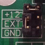 Supplies 12vdc when activated. "C" pin is ground. (Factory default selection) |
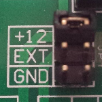 Supplies 12vdc when activated. "C" pin is not connected. |
| The jumper is located behind the relay connectors. The factory default is to provide 12vdc when the relays are activated and should cover most installations. To change the common selection, remove the 4 screws from the rear panel and slide the board out far enough to access the jumpers. Shown to the right are 4 selection options. |
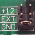 Switches to ground when activated. "C" pin is not connected. |
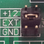 Connects to the power source on the "C" pin |
Relay output connections
Relay connections are made via the pluggable 7-pin connectors on older units and to integrated screw terminals on later units. No soldering is required. Each connector has outputs for 6 relays. The relay outputs are labeled 1 thru 12. The G pin is ground and the C pin is for an external voltage, if desired. Attach the control wires by inserting them into the holes in the connector plug and tightening the screw to secure them.
Configuration
Configuring the radio
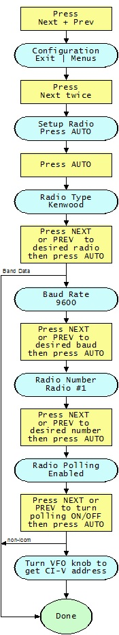 Enter configuration modeThe configuration menus are entered by pressing the NEXT and PREV buttons at the same time. The Configuration screen should be displayed. The Next and Previous buttons are now used to move between the various configuration menus. When at the Configuration screen pressing PREV will exit the configuration mode. Begin radio configurationPress NEXT twice to move to the Setup Radio screen. (or PREV if you have already passed it). When the Setup Radio screen is showing press AUTO to begin configuring the radio interface. NOTE: For Icom radios you must have CI/V Transceive enabled to complete the configuration process. Set radio numberThe first item to set is the radio number. For the 1x8 swtich you must select Radio #1. For the 2x8 switches you may select either Radio #1 or Radio #2. If you are using the 4x8 switch you may select radio numbers 1 thru 4. Press AUTO when finished. Set radio typeAfter pressing AUTO to set the radio number the Radio Type screen will appear. Cycle through the selections using the Next and Previous buttons. Press AUTO when the desired radio type is selected. The Yaesua nd Kenwood selections offer a FA and IF option. Choose the one used by your logging software. If in doubt use the FA selection for using the frequency on VFO A. If Band Data was selected you are now finished with the radio configuration. For all other radio type the Baud Rate screen will now be shown. Set radio baud rateAfter selecting the radio type you must select the radio baud rate. This baud rate applies to both the RS-232 and USB connections. Use Next and Previous to step between the selections. Press AUTO when the desired baud rate is selected. The Radio Number screen will now be displayed. Set radio pollingAfter selecting the baud rate you must set the radio polling. Press Next or Previous toggle between Enabled and Disabled. Leave polling enabled except under special circumstances. When polling is disabled you must have your logging or radio control software poll the radio or the band decoder will not function. Press AUTO when finished. Except for Icom radios this completes the radio configuration process. Acquire CI-V address (Icom only)The SM-8 automatically acquires the CI-V address of Icom radios after exiting the radio configuration. This requires the CI-V Transceive function on the radio to be enabled. The acquired address will be displayed. |
Configure the relays and antennas
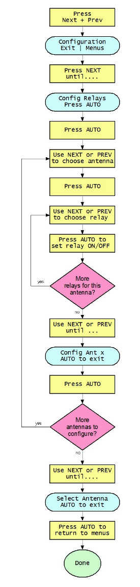 Enter configuration modeThe configuration menus are entered by pressing the NEXT and PREV buttons at the same time. The Configuration screen should be displayed. The Next and Previous buttons are now used to move between the various configuration menus. When at the Configuration screen pressing PREV will exit the configuration mode. Begin relay configurationPress NEXT four times to move to the Config Relays screen. (or PREV if you have already passed it. Press AUTO when the Config Relays screen is displayed. Select antenna to configurePress NEXT or PREV to select the antenna to configure. The exit screen is located between Antenna 1 and Antenna 16. Press AUTO when the desired antenna is selected. Select relays for antennaUse NEXT and PREV to move among the 12 relays. Press AUTO to toggle
the relay ON / OFF. When finished configuring an antenna, press NEXT or
PREV to the exit screen which is located between Relay 1 and Relay 12.
Press AUTO to return to the Config Antenna screen. Use NEXT or PREV to
select the next antenna to configure and repeat the process for each
relay. |
Assigning the antennas
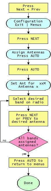
You must first configure the radio before you can assign
antennas to each band as the band to be configured is selected
by changing bands on the radio. Enter configuration mode The configuration menus are entered by pressing Next and
Previous at the same time. The Next and Previous buttons are now used to
move between the various configuration menus. When at the Configuration
screen pressing Previous will exit the configuration mode. Press AUTO to
begin assigning antennas to each band. Set antenna for each bandYou must configure the radio before assigning antennas as the band to configure is set by the radio. Place the radio on the band to be configured and then, using the NEXT and PREV buttons, select the antenna for the current band. Selections are automatically saved. Switch the radio to the next band and select the desired antenna. Do this for each band. Press AUTO when finished. |
Advanced features
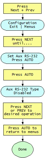 Aux RS-232 data stream When the RS-232 connection on the radio connector is not being
used by your radio, such as Icom, band data or Flex SDR on USB, the SM-8
can automatically generate a data stream on the RS-232 pins in either
Kenwood or Yaesu format. This is useful for automatically controlling
station accessories. You may choose either the FA or IF data formats.
The one to choose depends on the device using this data stream. The baud
rate is fixed at 9600.
|
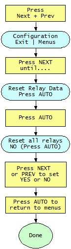 Reset relay data The Reset Relay Data function is used to reset the relay
configuration for all antenna to the factory default of Relay 1 for
Antenna 1, Relay 2 for Antenna 2, etc. Antennas 13 thru 16 will have no
relays assigned to them. |
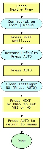 Restore defaults The Restore Defaults function will clear all user data and
restore them to factory defaults. Be aware that using this function will
erase all of your settings. |